Fluid pumping systems are fickle things to get right. You may think you have the right answer on paper, engineer every safety feature you can imagine, and then watch reality smack you in the face when you turn the pump on, and the system fails to perform as intended. Or, more commonly, it works close enough to specification to check the performance box, but the pump is running in a less than ideal place on its curve and becomes a maintenance nightmare to keep in service.
A variety of causes can land you in this scenario, but the most common one is making bad assumptions about your system or having an incomplete data set on which to base your pump selection. The situation described is one in which flow modeling software can drastically increase the accuracy and efficiency of the front-end work required to design a pumping system, or to correct long-standing assumptions about an existing system.
What follows is an excellent example of how West View Cunningham has used AFT Fathom (our software of choice) to help design a mixture of blank sheet capital projects and retrofit/modify an existing system for new duty conditions.
Background
At the end of 2018, a customer in the steel industry approached us to help him design an upgraded recirculation system for his company’s plate acid pickling tubs. We would be responsible for moving a moderately large volume flow (600gpm) of mixed acids at elevated temperatures with an up to 18ft suction lift in a recirculation flow, while also needing to create enough pressure on the pump’s discharge to send a side stream across the plant into their new acid filtration unit. Getting the calculations right on what the NPSHa (See our blog post about the importance of NPSH) would be for this system under realistic running conditions was critical in designing a pump and control strategy that met the customer’s exacting specifications.
Our customer had an existing system in place which we needed to use as a starting point in the design. Their system worked, but not as well as they wanted it to perform. The primary issue was that when the pickling tanks needed to be drained of acid, and the pumps being used could only drain roughly 2/3 of the tanks’ volume before the pumps would lose prime. At that point, a vacuum truck needed to finish draining the tanks, which required more time and money than the customer wanted to spend turning over acid bi-weekly.
This project’s biggest challenge was never having enough information from which to work. Our customer had zero visibility of the existing system’s mechanical parameters when it was running – no pressure gauges nor flow meters. The best data we could get was the approximate time it took to drain a fixed volume and an amp reading off the motor when the pumps turned on. We did a system walk-down and modeled the piping as close to reality as possible.
Through a long revisions process, we created a model that was close enough to the reported running conditions that we could use the model as a baseline for what we would ultimately identify as critical upgrades required to make the new system work as intended.
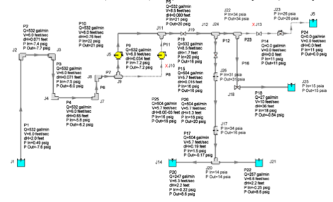
Figure 1. Final flow model output, showing the flow path of 1 of 3 pickling tanks.
Solving a Puzzle
In Figure 1 above, you can see our major mechanical design challenge. Flow starts in the lower left reservoir and is pulled up 18 feet through a gooseneck over the edge of the pickling tub. The low-pressure area at the top of the gooseneck required us to consider it carefully in our design.
That’s because pumping the acid mixture too fast relative to the pipe size would cause the pressure in that section of pipe to drop below the fluid’s minimum vapor pressure, and cause the liquid to boil and split the fluid column in the pipe, causing the prime to break.
The first step in changing the system’s design was to identify what we could change. We had to deal with three separate tanks:
- Tank 1, a mixture of nitric and hydrofluoric acids at roughly 20% concentration combined, running at 135°F
- Tank 2, sulfuric acid at roughly 18% concentration, running at 155°F
- Tank 3, running rinse water with waste acids mixed in, running at 120°F
The largest contributing factor to the vapor pressure of these acid/water mixtures was the fluid temperatures – a parameter we were not allowed to change.
The only major variables we had permission to change were:
- Inlet Piping Size
- Geometry (within size restrictions)
- Pump Size
- Impeller Geometry
- Speed
Altogether, we modeled and tested 150+ different combinations of piping configurations with different impellers and VFD speeds. We eventually settled on a robust solution that checked all the customer’s boxes and moved forward with the design.
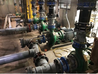
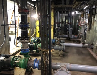
Figure 2 6x New KF6410 Ansimag pumps installed
We installed the pumps in early 2020 and commissioned them in October of last year. Although our initial models were not exact matches to the final installed configuration, with some quick adjustments made onsite, we got the model output to match within 3% of the values we were seeing on the plant’s instruments.
Based on our data, we were able to tell the system controls contractors what set points they needed to program to have the pump run reliably. To date, we’ve had six months of trouble-free system operation.
None of our initial work on this project would have been possible without modeling software to verify the existing system’s conditions and fill in the blanks of the dataset our customer provided. The final design was similarly only possible to engineer because of the rapid and iterative design and testing that flow modeling allows.
If you need answers to difficult hydraulics questions or “problem-child” applications…